Six stages carry a melt from ore or scrap to a bar you can order: making, refining, casting, forming, heat treatment and finishing. Every figure on this page comes from the source report; nothing is averaged or smoothed over.
Stage 1 of 6
Primary steelmaking
Iron is either reduced from ore in a blast furnace or melted from scrap in an electric arc furnace.
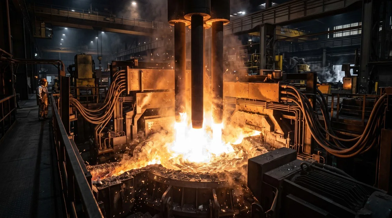
Stage 1: Primary steelmaking process illustration.
Steel starts one of two ways. The integrated route reduces iron ore with carbon and then burns the carbon back out with oxygen. The electric route melts scrap and direct reduced iron with an electric arc. Most stainless made today comes off the electric route, because stainless scrap is worth recovering.
Both routes finish in the same place: a bath of liquid steel at roughly 1 650 °C, carrying too much carbon and not yet holding its alloy specification. That is what secondary refining is for.
Hot metal tap1 450–1 500 °C
Carbon in, carbon out4,5% to 0,03%
Arc plasmaover 3 500 °C
Blast furnace and basic oxygen furnace
Ore, coke and limestone are charged into the furnace top while preheated air is blown in at the bottom.
Preheated air at 1 100–1 250 °C, enriched with oxygen and pulverised coal, enters through water-cooled copper tuyères.
Carbon monoxide reduces the ore in stages: 3Fe₂O₃ to 2Fe₃O₄ at 400–600 °C, Fe₃O₄ to 3FeO at 600–800 °C, then FeO to Fe above 800 °C.
Tapped hot metal leaves at 1 450–1 500 °C carrying about 4,0–4,5% carbon, 0,3–0,8% silicon, 0,4–1,0% manganese, 0,08–0,15% phosphorus and 0,03–0,08% sulphur.
In the converter, hot metal makes up 75–85% of the charge and scrap the rest, acting as a coolant. Oxygen above 99,5% purity is blown at Mach 2,0–2,4 and burns the carbon out exothermically.
Slag basicity, the ratio of calcium oxide to silica, runs 3,0–3,8 so phosphorus reports to the slag. The blow ends at 0,03–0,08% carbon and 1 640–1 680 °C.
Electric arc furnace
Graphite electrodes strike an arc through a charge of recycled scrap and direct reduced iron.
Arc plasma exceeds 3 500 °C and the furnace draws 350–450 kWh per tonne of electrical energy, supplemented by chemical energy injection.
Foaming slag practice injects carbon into the iron oxide in the slag, expanding slag volume by 200–300%.
The foam shields the sidewall refractories, stabilises the arc and lifts thermal efficiency from around 50% to over 70%.
Stage 2 of 6
Secondary refining
Ladle metallurgy sets the final chemistry: sulphur out, hydrogen out, carbon out, chromium kept.
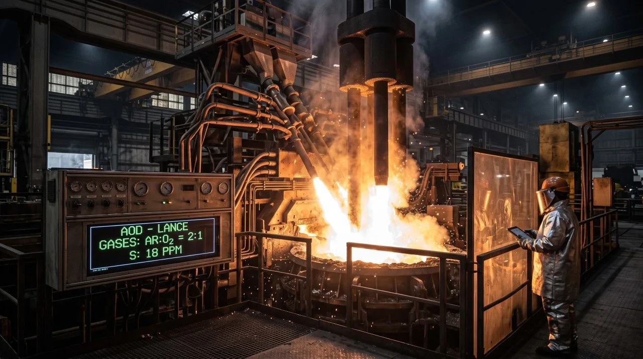
Stage 2: Secondary refining process illustration.
This is where a grade actually becomes that grade. The ladle furnace reheats and desulphurises, vacuum degassing strips dissolved gases, and argon oxygen decarburisation solves the problem that makes stainless difficult: how to burn carbon out of the bath without burning the chromium out with it.
Sulphurbelow 20 ppm
Hydrogenbelow 2,0 ppm
Chromium recoveryover 98,5%
Ladle furnace
Arc reheating and synthetic slag conditioning, under reducing conditions.
Deep desulphurisation drives sulphur below 0,002%, under 20 parts per million.
Calcium silicide wire injection turns solid alumina and calcium sulphide inclusions into spherical, low-melting-point liquid calcium aluminates.
Vacuum degassing
The melt is exposed to deep vacuum below 1,33 mbar to strip dissolved gases.
Hydrogen falls below 1,5–2,0 parts per million, which is what prevents delayed hydrogen flaking in heavy forgings.
Vacuum carbon deoxidation drives carbon and oxygen to carbon monoxide gas, removing oxygen without forming solid oxide inclusions.
Argon oxygen decarburisation
The step that makes stainless possible: dilute the oxygen blow with argon.
Carbon and chromium both want the oxygen. Diluting the blow with argon lowers the partial pressure of carbon monoxide, which shifts the balance towards oxidising carbon instead of chromium.
The oxygen to argon ratio steps down through the blow: 3:1, then 2:1, 1:1 and finally 1:3.
Carbon ends below 0,015%. A ferrosilicon and lime reduction returns any oxidised chromium to the bath at better than 98,5% yield.
Vacuum oxygen decarburisation
For the extra-low carbon and nitrogen grades, under vacuum below 20 mbar.
Reaches carbon at or below 0,010% and nitrogen at or below 0,008%.
This is the route behind the L grades, where low carbon is what prevents weld decay.
Stage 3 of 6
Casting and solidification
Liquid steel is frozen into a strand or an ingot, and the way it freezes decides its soundness.
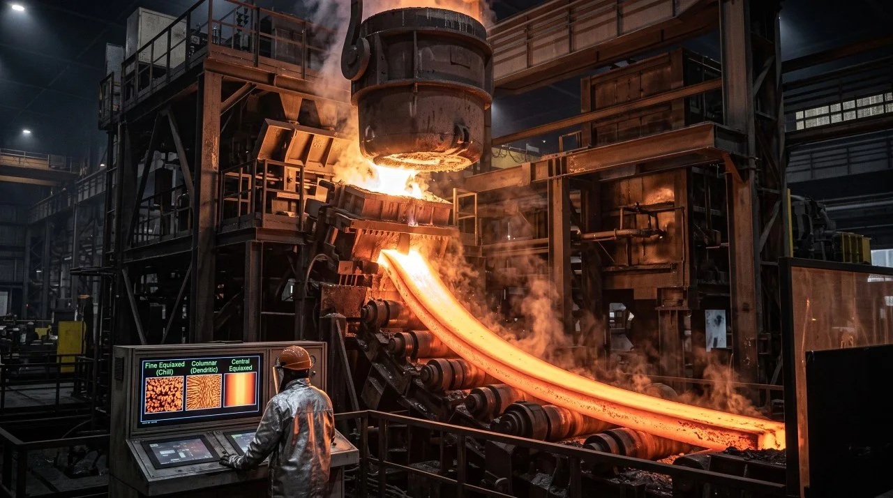
Stage 3: Casting and solidification process illustration.
Steel does not freeze uniformly. Against the cold mould wall it chills into fine equiaxed grains, then grows inward as long columnar dendrites following the heat flow, and finally freezes as equiaxed grains in the centre where the last liquid sits. That last liquid carries the segregated impurities, which is why the centreline is the part worth engineering around.
Chill zonefine equiaxed
Columnar zonedendritic growth
Corecentral equiaxed
Continuous casting
Steel flows ladle to tundish to an oscillating water-cooled copper mould through a submerged entry nozzle.
Three solidification zones form in sequence: a chilled equiaxed shell, a columnar dendritic zone, and a central equiaxed core.
Dynamic soft reduction squeezes the strand at the final point of solidification, suppressing centreline segregation and shrinkage porosity.
Formats follow the product: slabs for plate and sheet, blooms for beams and rails, billets for bar and wire.
Ingot casting
Bottom or top pouring into cast iron moulds with refractory hot tops.
The hot top feeds the shrinkage cavity, keeping the pipe out of the usable body of the ingot.
Reserved for massive rotor forgings above 100 tonnes and for specialised tool steels.
Stage 4 of 6
Forming and rolling
Hot rolling refines the grain. Cold rolling work-hardens it and buys tolerance and finish.
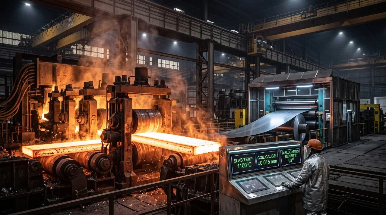
Stage 4: Forming and rolling process illustration.
The difference is the recrystallisation temperature. Roll above it and the grains reform continuously as they deform, so the steel stays soft and the structure refines. Roll below it and the dislocations pile up instead, which is what makes cold-rolled material stronger, harder and less ductile than the same grade hot-rolled.
Hot entry1 050–1 250 °C
Dislocation density10⁸ to 10¹³ per cm²
Cold gauge tolerance±0,005–0,025 mm
Hot rolling
Entry at 1 050–1 250 °C, finishing at 850–950 °C, above the recrystallisation temperature.
Dynamic and static recrystallisation refine the grain structure while flow stresses stay low.
High-pressure descaling jets at 180–250 bar strip the primary mill scale.
Cold rolling
At ambient temperature, below 100 °C.
Work hardening multiplies dislocation density from about 10⁸ per cm² to 10¹¹–10¹³ per cm², raising tensile and yield strength sharply.
Sendzimir twenty-high cluster mills hold gauge to ±0,005–0,025 mm.
Surface roughness comes down to Ra 0,1–0,8 µm, which is where the 2B finish comes from.
Stage 5 of 6
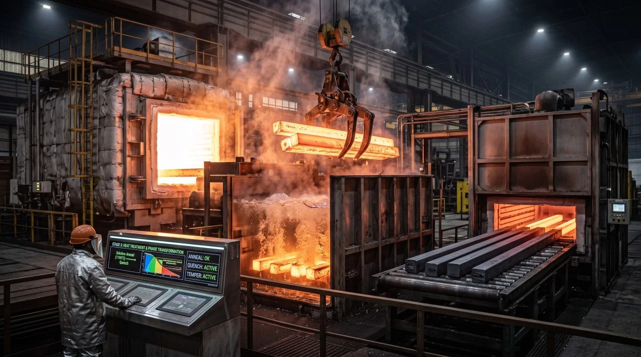
Heat treatment and phase transformation
Solution annealing dissolves carbides and quenches them out of the way. Quenching and tempering builds martensite, then makes it usable.
Stage 5: Heat treatment and phase transformation process illustration.
Two opposite intentions share one furnace. In austenitic and duplex stainless the aim is to dissolve everything harmful and cool fast enough that it cannot come back. In martensitic and alloy steels the aim is the opposite: cool fast enough to force a hard, distorted structure into existence, then temper it back to something tough enough to use.
Both hinge on avoiding or hitting a specific temperature window on the way down, which is why the cooling curve matters more than the peak temperature.
Solution anneal1 040–1 150 °C
Sensitisation window450–850 °C
Temper range150–650 °C
Solution annealing
For austenitic and duplex stainless: heat to 1 040–1 150 °C, then quench.
Dissolves chromium carbides and the sigma and chi intermetallics back into the austenite matrix.
Rapid water quenching carries the steel through the 450–850 °C sensitisation window too quickly for carbides to re-precipitate at the grain boundaries.
Skip the quench and chromium-depleted zones form along the boundaries, which is exactly what intergranular corrosion attacks.
Quenching and tempering
For martensitic and alloy steels: austenitise above Ac₃, then quench hard.
Quenching fast enough to miss the diffusion nose produces body-centred tetragonal martensite, which is hard and brittle.
Tempering between 150 °C and 650 °C relieves macro-stress and precipitates transition carbides or stable cementite and alloy carbides, restoring toughness and ductility.
The tempering temperature is the dial: higher temper, lower hardness, more toughness.
Normalising and full annealing
For carbon steels, where the cooling rate sets the structure.
Normalising, air cooling from above Ac₃, gives a fine and uniform ferrite and pearlite structure.
Full annealing, slow furnace cooling, gives soft coarse lamellar pearlite for cold forming.
Stage 6 of 6
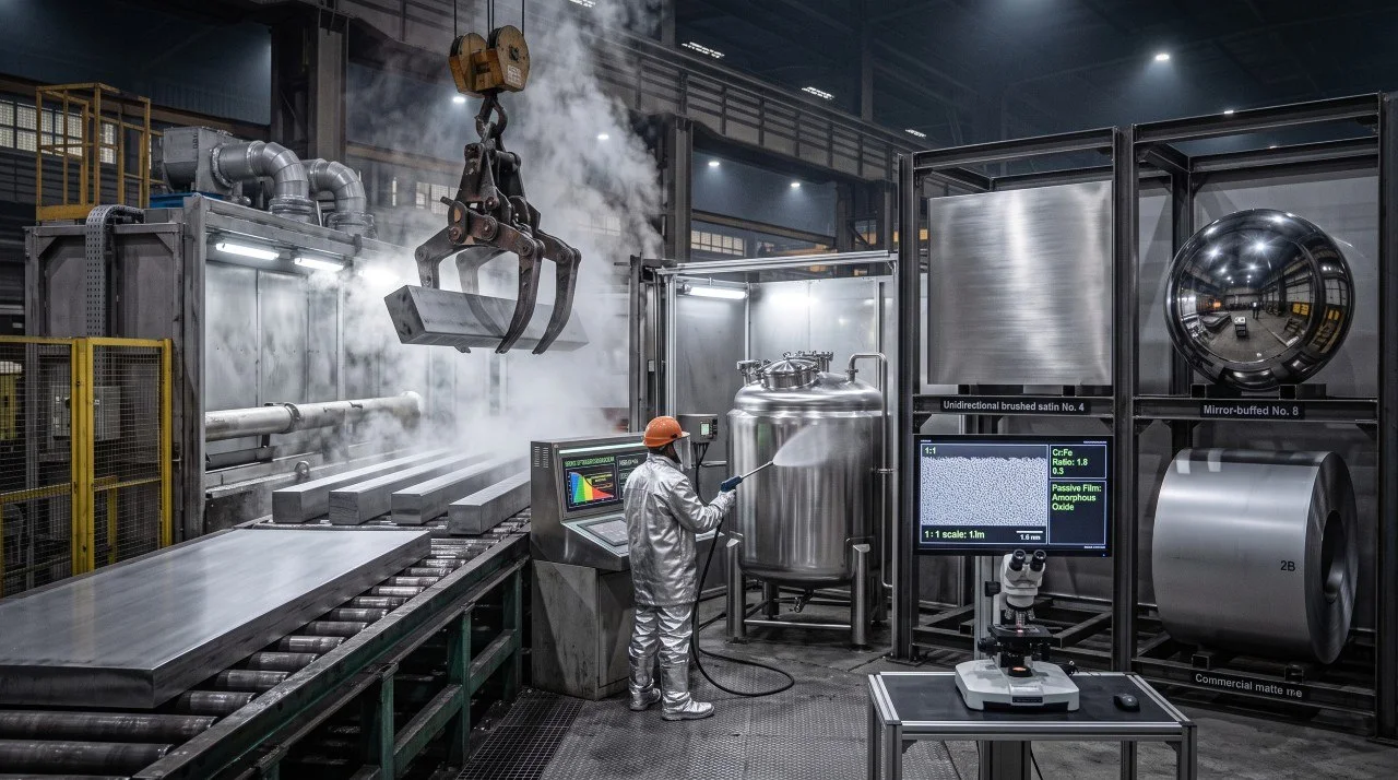
Surface finishing and passivation
Pickling strips the scale and the chromium-poor layer beneath it, and the passive film rebuilds itself in air.
Stage 6: Surface finishing and passivation process illustration.
Stainless is not corrosion resistant because chromium does not corrode. It is corrosion resistant because chromium corrodes immediately, into a film one to three nanometres thick that then stops anything else getting through. Damage it and it reforms. The whole point of pickling and passivation is to make sure the surface underneath is clean enough for that film to form properly.
Passive film1–3 nm
Chromium to iron ratioabove 1,5
Galvanising bath445–455 °C
Acid pickling and passivation
Mixed acid baths of 10–15% nitric acid and 1,5–3,5% hydrofluoric acid at 50–65 °C.
Dissolves the scale and the chromium-depleted layer directly beneath it.
Passivation in nitric or citric acid leaches free iron from the surface.
The result is a 1–3 nm amorphous, self-healing hydrated chromium oxide film with a chromium to iron ratio above 1,5.
Hot-dip galvanising
Molten zinc immersion at 445–455 °C, for carbon steel.
Iron and zinc form intermetallic layers in sequence: gamma, delta, zeta, then a top layer of pure zinc.
Protection is sacrificial, so the coating corrodes in place of the steel even where it is scratched through.
Standard mechanical finishes
The finishes a stockist actually quotes on.
No. 1: hot rolled, annealed and pickled, matte.
2B: cold rolled, annealed, pickled and given a light skin pass. The standard commercial finish.
Compiled from the metallurgical research report behind this knowledge base, section by section. It explains the process window, not the certificate for a specific heat.
The specifications and data on this site are provided for general information only. Verify any real-world project with a qualified metallurgist before relying on these figures. We take no responsibility for the use and application of this information.